

Hi, as I said in other posts, the best way to have a radio that just works in the 2017 Impreza is to ditch the OEM one and buy an aftermarket. In this post, I'll explain which wires do what and how I got the rear camera working on the cheap.
Standard disclaimer: I'm not responsible if you screw up something. This info is given out of good will, to the best of my knowledge. I'm not a profesionnal, only an amateur (with 23 years of mobile sound system background). Don't come to cry if you burn your car down and your wife leaves with the kid :crying:
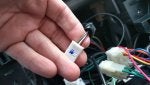
Ok, so there is a plug dedicated to the rear camera. It's the 5 pin one, with only 4 wires in it. The pin goes as follow. Beware, the colors don't match what is usually Positive and ground:
Black = +6 volts from OEM radio
Red = Ground of +6 Volts from radio
White = Camera Signal + (would be center wire on an RCA wire)
Grey/Black = Camera Signal - (would be exterior wire/shield on an RCA wire)
Now, you read correctly, the camera is powered by a +6 volts supply from the radio. I plugged back the radio and mesure it. Again, the Black is really +6V and Red is it's Ground
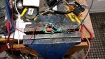
So to power this, you can buy a 12v --> 6v stepdown module. I did'nt have one but I had an extra phone charger. It gave +5.2Volts and is rated at 500 milliamps (0.5 amp). I figure, why not try it. Worst case it camera will be erratic and I'll buy the real thing. I cracked it open and replace the input connector on the PCB with straight wires. Same with the +5v output wires. I then taped up everything, that is the entire voltage converter, so there's not short. I plugged the camera power supply on the Switched +12v going to radio. It's the Red one on the aftermarket radio harness. Ground is black, or any chassis bolt.
I then found an RCA wire and cut the wire. The outer wire (shielding) is the outside of connector and the center wire is the center plug.
Then, hook everything up as per the list above.
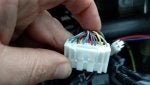
For the Reverse Signal, it's on the 28 pins connector. It's Pin #2, Green wire. Connector facing you, wires away from you, retaining clip on the top. Pin numbering goes as follow:
01-02-03-04-05-06-07-08-09-10-11-12-13-14
15-16-17-18-19-20-21-22-23-24-25-26-27-28
Check last picture, it's the green wire on the left. It giving +12V when on car is on Reverse. 0 Volt when on any other gear.
And Voilà!
Possible plug-in solution:
While searching for a suitable harness instead of pulling pins from the OEM harness, I found that Scosches produce what appear to be a plug-in solution. Module #CRTSU01. I did not use it or try it but it looks very much like the real thing. 5 pins connector, a video out, a box for a 6 volts stepdown converter. It's worth about 25$ US dollars on Amazon.com as I type this.
http://www.scosche.com/crtsu01#product_tabs_user_guide
If one tries it, I would be very curious to hear about it!
Standard disclaimer: I'm not responsible if you screw up something. This info is given out of good will, to the best of my knowledge. I'm not a profesionnal, only an amateur (with 23 years of mobile sound system background). Don't come to cry if you burn your car down and your wife leaves with the kid :crying:
Ok, so there is a plug dedicated to the rear camera. It's the 5 pin one, with only 4 wires in it. The pin goes as follow. Beware, the colors don't match what is usually Positive and ground:
Black = +6 volts from OEM radio
Red = Ground of +6 Volts from radio
White = Camera Signal + (would be center wire on an RCA wire)
Grey/Black = Camera Signal - (would be exterior wire/shield on an RCA wire)
Now, you read correctly, the camera is powered by a +6 volts supply from the radio. I plugged back the radio and mesure it. Again, the Black is really +6V and Red is it's Ground
So to power this, you can buy a 12v --> 6v stepdown module. I did'nt have one but I had an extra phone charger. It gave +5.2Volts and is rated at 500 milliamps (0.5 amp). I figure, why not try it. Worst case it camera will be erratic and I'll buy the real thing. I cracked it open and replace the input connector on the PCB with straight wires. Same with the +5v output wires. I then taped up everything, that is the entire voltage converter, so there's not short. I plugged the camera power supply on the Switched +12v going to radio. It's the Red one on the aftermarket radio harness. Ground is black, or any chassis bolt.
I then found an RCA wire and cut the wire. The outer wire (shielding) is the outside of connector and the center wire is the center plug.
Then, hook everything up as per the list above.
For the Reverse Signal, it's on the 28 pins connector. It's Pin #2, Green wire. Connector facing you, wires away from you, retaining clip on the top. Pin numbering goes as follow:
01-02-03-04-05-06-07-08-09-10-11-12-13-14
15-16-17-18-19-20-21-22-23-24-25-26-27-28
Check last picture, it's the green wire on the left. It giving +12V when on car is on Reverse. 0 Volt when on any other gear.
And Voilà!
Possible plug-in solution:
While searching for a suitable harness instead of pulling pins from the OEM harness, I found that Scosches produce what appear to be a plug-in solution. Module #CRTSU01. I did not use it or try it but it looks very much like the real thing. 5 pins connector, a video out, a box for a 6 volts stepdown converter. It's worth about 25$ US dollars on Amazon.com as I type this.
http://www.scosche.com/crtsu01#product_tabs_user_guide
If one tries it, I would be very curious to hear about it!


")